关于modelsim仿真
modelsim是单内核支持VHDL和Verilog HDL混合仿真的仿真器,是做FPGA/ASIC设计的RTL级和门级电路仿真的好选择。modelsim仿真
本身就是编写testbench的过程。通过Testbench模块向待测模块输出信号作为激励,同时接收从待测模块输出的信号来查看结果。本文
介绍如何实现Verilog HDL仿真。
步骤
打开modelsim软件,选择File->new->Library…,出现如图1-1所示的界面创建库,
选择 a new library and a logical mapping to it , 在Library Name 下写work,点击ok。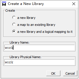
接下来选择 File->new->Project… , 出现如图1-2所示的界面创建工程环境。
依次为工程文件名,文件存放位置,所在的库。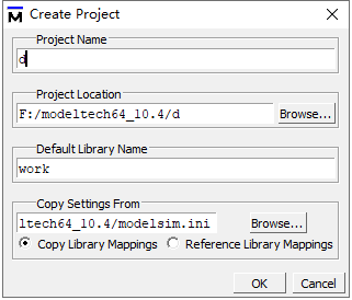
在空白处右击,选择Add To Project->Existing File… ,出现如图1-3所示的界面,
点击Browse…,选择所仿真的文件,这里我选择的文件c.v代码在下面。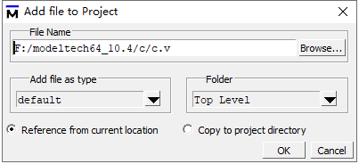
点击new file ,在软件右侧出现文本框,输入以下代码进行保存,文件名与module后的名字一样如下面代码tb2.v。
`timescale 1ns/1ns
`include"./c.v"
module tb2;
reg clk;
wire L1,L2;
initial
begin
clk=0;
end
always #10 clk=~clk;
c i1(.clk(clk),.L1(L1),.L2(L2));
endmodule
`timescale 1ns/1ns 是用来时间轴设置的,这里表示仿真的时间轴单位是1ns,仿真工具仿真的最大精度只到1ns内的逻辑变化。
待测模块中的reg型信号在Testbench中就变成了wire,待测模块中的wire型信号在Testbench中则对应为reg型。
initial 表示初始化。
always #10 clk=~clk;是用来时钟产生的,这里表示每10ns(与时间轴设置有关),clk来一次高低电平转换。
c i1(.clk(clk),.L1(L1),.L2(L2));c是我们想要仿真的模块,il是我们创建的对象名,类似于java中的类与对象关系。完成保存后,按照3的步骤将tb2.v添加进来。然后鼠标右击,选择Compile->Compile All,界面出现如图1-4 所示,
如果左下角出现红色字体,说明模块编译错误。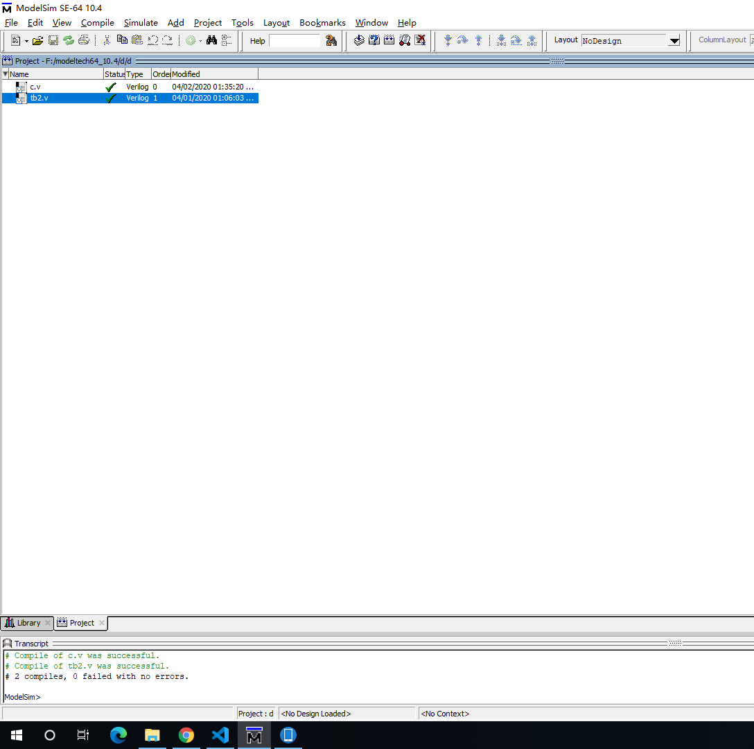
点击左下角Library,选择work->tb2,右击Simulate,如果work为空,重启该软件。完成后,选择左侧的il,右击选择Add All。出现图1-5所示的界面。
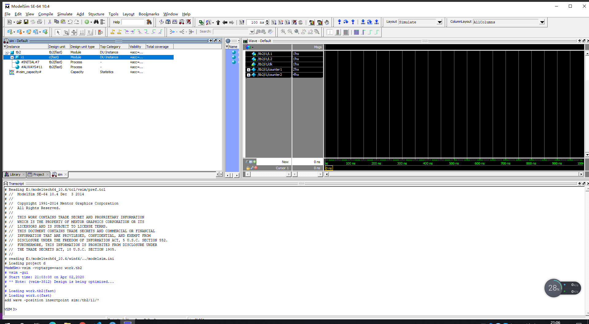
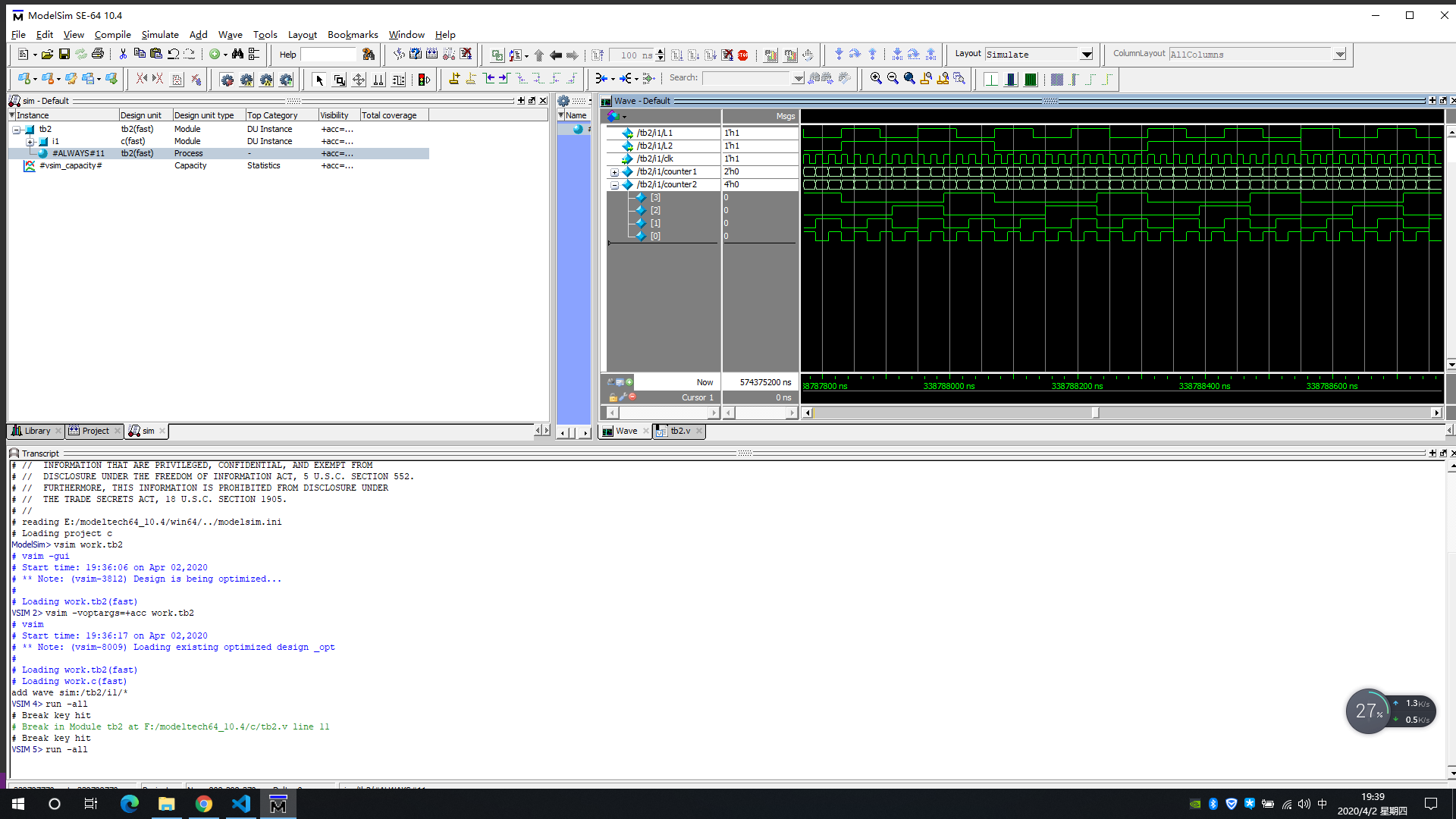
最后选择Simulate->Run->Run-All,然后点击Wave -default下的变量,出现下图1-6运行的仿真。
代码 c.v
 module c(L1,L2,clk);
  output L1,L2;
  input clk;
  reg L1,L2;
  reg[1:0] counter1;
  reg[3:0] counter2;
  initial
   begin
    L1=1'b1;
    L2=1'b1;
    counter1=0;
    counter2=0;
   end
  always@(posedge clk)
   begin
    counter1=counter1+1;
    if(counter1==2'd3)
     begin
      L1=~L1;
      counter1=0;
     end
   end
  always@(posedge clk)
   begin
    counter2=counter2+1;
    if(counter2==4'd12)
     begin
      L2=~L2;
      counter2=0;
     end
   end
 endmodule